
Summer is in full swing here in the Hudson Valley, alternating between humid rainy days, and blindingly hot humid sunny days. Did I mention humid? So once again, on the drier days I’m out whenever possible with one of the portable setups doing a little operating. In these times of rock bottom propagation, QRP does present a challenge. Between that and the humidity, a guy can get restless.
I have not been interested at all up to now in the recent ham phenomenon of FT8. I have done digital modes in the past, most notably PSK-31, but in recent years my interest dropped off. The current controversies over FT8 being “real ham radio” were enough to fend me off. But, to be fair I should not make up my mind about it until I tried it. So I started to think, not seriously of course, about what it would take to try out FT8. Just to be sure I have no interest in it whatsoever.
Well the first thing I would need was a computer to run the software. All of the machines in our household are spoken for, and it would inconvenient to move my office laptop for digital shack duties, so I started the usual eBay search for an old, used, cheap, Linux worthy laptop. Pretty depressing.
I’m not sure when the idea occurred to me, but for less than half the money and one quarter the footprint, a Raspberry Pi might do the trick. The new models of this $35 single board computer run quad core processors at 1.2 GHz, a far cry from the original. It was an intriguing idea, and I took a look. I found a lot of material, much of it on Youtube. There are dozens of videos covering all facets of Raspberry Pi mischief: I used several of them as sources for my project and I will share the links as I go along.
One of the Youtube channels I found, SurvivalTechNord by Julian, OH8STN, suddenly changed the whole idea and crystallized the project for me. I highly recommend his work, the videos are packed with great information.
Running digital modes would be interesting, but running them portable, off grid, battery operated QRP would be awesome! I had to do this, especially since I instantly knew that I had the perfect substrate for a portable digital platform: a bamboo cutting board.
I’ve put lots of projects on these boards – they’re cheap, readily available in the produce section of your local grocery, and made from a renewable resource. Every project is better on a bamboo cutting board.
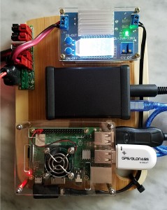
Everything’s better on a bamboo cutting board
I made a list of the hardware I would need:
- bamboo cutting board (had one in stock)
- Raspberry Pi (I chose to use a 3B+ rather than the newly released 4)
- case for the Pi
- power distribution for 12v to the radio and the Pi
- DC-DC converter to supply 5v to the Pi
- sound card interface
- rig control interface
- GPS (for off grid time synchronization)
- FT-817
- android tablet for UI (Raspberry Pi runs “headless”)
- one of those cute bluetooth keyboard/mouse combos (optional, but handy)
- 12v battery to run everything (I have a Bioenno 4.5Ah lipo)
- several class 10 micro SD cards and USB reader (really important, make backups!)
There’s a lot to describe about this project, so I’m going to focus on the hardware in this post, and add follow on posts to discuss some other key issues:
- setting the Raspberry Pi up to run headless
- installing the latest versions of ham radio digital software
- setting the Pi up as an access point when there isn’t Wifi available
Anyway, on to the hardware. By watching Julian’s videos, I selected the sound card interface and the GPS unit for the project.
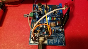
The sound card interface, a ZLP MiniProSC, is sold by a firm in the UK, but ordering it for delivery to the States was not a problem, and it was about a week from order to delivery. The MiniProSc is tiny, has very good specifications, and no knobs. Audio levels are controlled from the computer, very convenient. The other choice was a Signal Link, which is more expensive, physically larger, and after reading reviews and comparing specifications, less attractive to me.
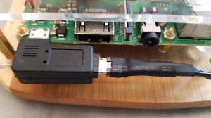
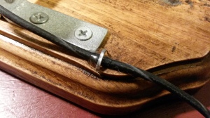
The MiniProSC is shipped with connecting cables for the radio of your choice. I ordered the data input cable for the FT-817, which will also work with my FT-847. Oddly enough, the MiniProSC uses the old style larger type B USB cable. There is nothing special about the bright blue one you see in the photo, it was just the shortest cable of this variety I had on hand.
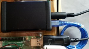
The MiniProSC
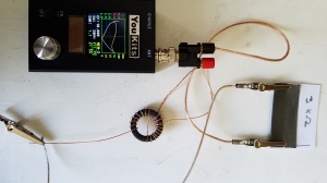
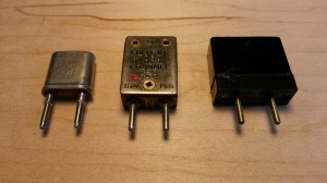
The GPS unit is a inexpensive USB dongle readily available on Amazon (here). Julian provides a video showing the software installation and setup necessary to allow Raspbian Linux to synchonize it’s system time to the NMEA sentences coming from the GPS. You will only need this when not connected to the internet; when you have an internet connection the time servers in the cloud provide more accurate time fixes and the GPS is ignored.
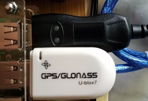
GPS and rig control dongles
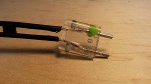
Julian also mentions an excellent Anderson Powerpole distribution block sold as a kit by K9JEB, John. These are a superb alternative to commercially made distribution blocks, and John offers an optional DC-DC converter the size of a Powerpole, which can be substituted in up to three locations on the board. I ordered my kit with one DC-DC converter, and the filter capacitors. This block allows me to connect the battery to the Raspberry Pi setup and the radio, and provides fused input. It works well, but I found that the Pi with all the USB devices connected wanted more current than the tiny converter could supply, and so consistently displayed the dreaded “lightning bolt” icon on the desktop indicating the supply voltage was sagging.
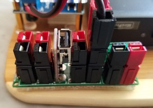
K9JEB power distribution block
Consequently I found a very nice, inexpensive adjustable DC-DC converter on Amazon (here). This works great, it can provide several amps if necessary with very good voltage regulation and includes a nice display and switch controlled start up. I haven’t noticed any switching noise on the perceptible on the ham bands. And, I can still charge my tablet from the DC converted on the power distribution block if I need to.
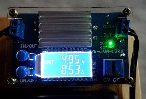
DC-DC converter
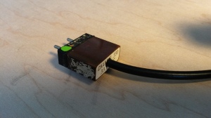
Connecting the Pi to the DC converter required making a power cable. I cannibalized an old wall wart for a two-wire cable that appeared robust enough to carry the amp or so we might draw on startup. The micro usb connectors are available on Amazon, about $3 for ten. You will need 10, because these things are really hard to solder to – the plastic melts easily if overheated. Use the finest soldering tip you have, crank the temp down, and use the minimum dwell time necessary to flow the solder. I added some heat shrink tubing for a strain relief, and a 90 degree usb adapter (Amazon, here) so I could route the cable with the least amount of stress. Some cable ties finish the job, once installed don’t mess with it. And make a few spares.
Homebrew micro USB cable and right angle adapter
Rig control is provided by an FTDI usb dongle (pictured above with the GPS dongle), again available from Amazon here. No problem if you stick with FTDI devices, no drivers needed for Raspian linux, it was truly plug and play. Not much to say, it just works.
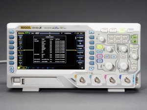
The Raspberry Pi is the 3B+ version, available just about everywhere. I decided to avoid the newer version 4, as there is a reported problem with powering it from the USB C cables available, requiring a converter from micro usb.
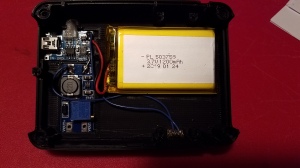
I found a nice case for it as well, that includes a heat sink set and a tiny fan that runs from the 5v GPIO pins. Looks classy. I was going to provide an Amazon link for it, but apparently the 3B+ version has been replaced the the version 4 case. Alas…
I chose to use 64 Gb micro SD cards for the persistent store on the Pi, but in retrospect that might be overkill; 32 Gb is plenty, you could probably get away with less. The issue is that you will need several of these cards so you can back up the software as you make progress with the various installation and configuration tasks. Trying to set up the access point I hosed up my setup several times, having those backups avoided the loss of hours of work.
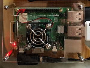
Raspberry Pi 3B+ in classy case
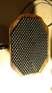
All this stuff needs to be stuck down to the cutting board, and my favorite medium for this is 3M Scotch brand “Extremely Strong” hook and loop fasteners. They don’t appear to have any other name, here’s the package:
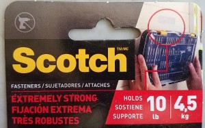
Scotch “Extermely Stong” fastener
There not actually hooks and loops, more like little mushrooms, and the tape is genderless. Clean both surfaces with a little isopropyl alcohol, let them dry. Stick to device, place carefully and stick to the board. Allow to set for a few hours undisturbed and your good to go. In the unlikely event that you ever want to remove something from the board, it can with effort be peeled off.
The idea of using the tablet, connected over wifi to the Pi as a user interface is brilliant. You can operate without direct connection to the rig giving you a lot of flexibility for your portable setup. The type of tablet does not matter; excellent VNC client apps are available free for Android and IOS devices which bring the Pi’s desktop to your device and allow you to interact with the ham radio software GUI. This photo is of my nVidia tablet running VNC client
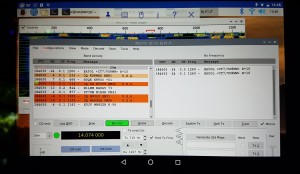
Rasberry Pi desktop running WSJTX on an Android tablet via VNC
While it is not necessary, these cute little bluetooth keyboard/mouse combinations (Amazon, here) eliminate the need to use the touch screen and virtual keyboar on your tablet, yielding finer and more positive control of the sofware in my opinion.
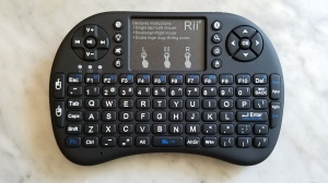
Cute Bluetooth keyboard
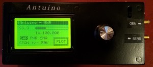
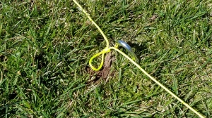
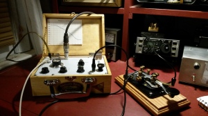
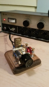
The rig is of course my venerable Yaesu FT-817 (original model) which has come out of mothballs and is ideal for this application. I have also used the board with my FT-847, the big brother of the 817, and this also works quite well.
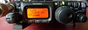
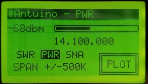
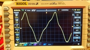
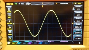
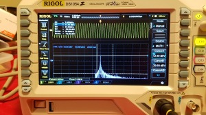
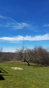
FT-817 listening to FT8 on 40m
I haven’t done tests but by rough calculation I should get 4 hours of operation from the 4.5 Ah battery. Once started, the Pi draws a steady 0.5 amp. The FT-817 draws about 2 amps at 5 watts on transmit. The receive current is about 350 ma. So in receive mode FT8 the setup is drawing about 850 ma, on transmit 2.35 amps. During QSO you have a 50% transmit/receive duty cycle, so the average QSO draw is 1175 ma. If you assume your time is spent two thirds listening and one third in QSO, overall average consumption would be 625 ma, and allowing for not depleting the battery much beyond 50% you could run for the setup for about 4 hours. More than enough for me.
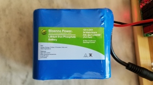
Bioenno 4.5 AH LiFePo Battery
In the next post I will go over the software used in the project. Lots of interesting stuff to talk about. Until then,
73,
de N2HTT


