
Summer is winding down, and a lovely summer it was. I think the weather here in the Northeast was the best I can remember for quite some time. Sure, we had some beastly hot, humid days, but on the whole it was great. A time to play outside, spend time with friends and family, and travel. Not so good for hanging around in a dark basement workshop, building radio gear.
Coming into the summer I had been working on a low voltage regen receiver, still a work in progress, and refurbishing the Knight V-44 VFO. The VFO needed lots of work, especially after I destroyed the main tuning coil with the careless application of an electric know (still slapping my forehead over that one.) At the beginning of June I got the coil rebuilt correctly, but was still not happy with the output into the Knight T-60. A friend of mine with access to a spectrum analyzer was going to help me out, but we didn’t get together then, and this became another project waiting for renewed attention.
But the summer was not without some ham radio excitement. The real attention-getter crept up on me unexpectedly. First, some back story:
About five years ago I discovered that Heathkit had manufactured kits in the late seventies for a CW transmitter/receiver pair. The receiver was released first, in 1978. All solid state, ham bands only with a switchable narrow filter, LSB/USB/CW, and built-in dial calibration. This was the HR-1680, and it was quite popular from the outset.
About two years later, the matching transmitter, the HX-1681 came out. CW only, no WARC bands, the transmitter was a hybrid – mostly solid state but with a tube final consisting of a pair of 6146’s that produced a full 100 watts out on 80 – 10 meters. Both units were housed in handsome matching heavy aluminium cases (Heathkit teal, of course) and both sported meters and main tuning dials that glowed red when illuminated. By slaving the receiver to the transmitter, smooth full break-in QSK was possible along with receiver muting and a sidetone. When I first heard of this pair, and researched them a bit I knew I had to have a set as my primary vintage rigs.

New arrival in the shack
While the receivers are relatively plentiful in the used market, the transmitters are hard to come by. Perhaps because of the delay in producing the kit, or maybe the CW-only capability, but it is my understanding that the transmitter did not sell well. They are hard to find used. Soon after buying the receiver, I located an auction for a 1681 but had to let it pass for financial reasons. On and off over the last five years I would see one of those transmitters come up on auction or in classifieds, but it was never the right time. Too expensive, or the seller was selling them as a pair and wouldn’t break up the station. It never quite worked out – until this Forth of July.
Maybe it was because most folks have more interesting things to do than watching eBay auctions on a big holiday weekend, or maybe the way the listing was worded it didn’t come up on the radar, but during the week leading up to the 4th I found an HX-1681 up for auction at a an extremely attractive price. Cosmetically a 9, and completely untested by the seller who did not have the required big iron power supply. I got the nod from management, and went for it. I won the auction at a very good price, and a week later my beautiful transmitter arrived.
Becoming a new owner of an HX-1681 brings new responsibilities. I also did not have the required big iron power supply, and that became the next imperative. The power supply is the Heathkit HP-23, later renamed the PS-23 after Honeywell threatened Heathkit with litigation over the HP mark. Several versions of this supply were made: the HP-23, then PS-23, PS-23A, PS-23B and finally PS-23C. There were minor user interface changes between the models, but basically they all supplied 12 vac for filaments, two plate voltages of 800 and 250 vdc, a negative bias voltage of -130 vdc, chassis ground and a switch line to allow the rig to turn the power supply on and off. These power supplies would work with all of the Heathkit tube rigs, requiring only minor tweaking to match any of the rigs.
One used to see these things by the dozens on eBay and on the classifieds, and could usually find them for well under $100, but recently they have become more scarce, and correspondingly more expensive. I shopped around for as long as I could, but the urge to be able to turn on my new transmitter was strong, and I wound up buying one for a little more than I normally would have, had I shopped longer. It was a clear win of instant gratification over common sense. Life is short, eat dessert first.
The unit I picked was a PS-23, one of the oldest and simplest models. Later models sport a switch for changing the low plate voltage between 250 and 275 volts. On this model it’s a hardwired change, which seemed to me an advantage – since I only needed the higher voltage, a convenient front panel switch that let you set the wrong voltage didn’t seem that necessary.

The wiring looked good
The unit I selected was not the cheapest around, but the photos showed that it had been recapped with modern plastic and aluminium electrolytic caps. Since the recap kits run about $60, I figured that was one additional expense I could avoid up front. The only real downside was the unit came with a home-made, dodgy looking connecting cable, instead of the usual 8-wire covered cable. Hey, the seller said it worked, what could go wrong?

Dodgy home-made cable
Okay, so the first thing I planned to do, before applying power to the 1681, was to go through the final resistance checks listed in the assembly manual. The manual itself was a bit of a challenge. Several years ago, it was common to find scans of Heathkit manuals online, but at some point someone acquired the intellectual property rights to the manuals, and began assiduously getting them off the web. Today it is difficult to find much more than schematics, and partial manuals online.
My 1681 did not come with a manual; all I had was a fragment of the assembly manual that described the resistance and initial voltage checks, alignment and adjustments, and basic operating instructions. Okay, that should be enough to get me going… until I realized that the resistance checks all referred to pictorials to locate test points, and I didn’t have the pictures. I needed to find a manual.
There are folks who sell paper facsimile manuals for specific Heathkit gear, and I was starting to look at those offerings, when I stumbled across an auction listing for someone selling a box full of unused Heathkit manuals. The assortment happened to include both the 1680 and 1681, with all diagrams and schematics, as well as manuals for some other toothsome Heathkit gear I don’t own (yet), all for a the price of a single facsimile. I couldn’t pass it up, and within a few days I had the manuals I needed along with the beginnings of a fine Heathkit library.

Lucky manual find
With the manual and pictures in hand, I opened up the 1681 and went through the resistance checks. The checks required verifying that a short to ground did not appear at a particular point, but did not specify the resistances you should see. All the checks passed but I was concerned about one resistance measurement which was about 3 ohms. That seemed awfully close to a short, and I spent about an hour tracing through the schematic before finding a 2.2 ohm resistor between the line and ground. Everything was okay.
The next phase was the initial voltage check. The 1681 is wired with a 3-wire AC cord, with the chassis grounded. I guess by the 1980’s this was already common practice. Older gear I have refurbished has come with 2-wire, non-polarized plugs – these are extremely dangerous, and the first thing I do when I find those is to rewire the gear with a 3-wire cord, chassis ground and inline fuse in the AC line. Not required this time, just saying…
So I powered up the PS-23, and did a careful check of the voltages supplied at the 11-pin socket. Everything looked good (I had already made the change for the 275 vdc low plate voltage) so I hooked the power cable, and turned on the 1681. The beautiful dial lights lit up red, and I immediately noticed a sizzling sound coming from the dodgy home-made cable. I don’t know about you, but when I hear sizzling sounds coming from a cable carrying more voltage than the third rail of the New York City Subway on one of the wires, I think “Abort! Abort!” That was the end of Voltage Test 1. Happily, there did not appear to be any damage to the rig or the power supply. Magic smoke intact, it was time to find a replacement cable.
Back to eBay, where there are perennial offers of a pair of 11-pin sockets and a six-foot length of 8-wire cable (this turns out to be a WireMan product BTW) which includes a helpful scan of the wiring instructions from the PS-23 manual. Assembling the cable was straightforward, and in short order I had a correctly wired, non-sizzling power cable for the HX-1681.

New cable and plugs
The initial voltage tests passed. This was the exciting moment, the first time I would try to load up the transmitter. Following the tune up instructions, I placed all the controls in the correct settings, and took the first step. Placing the meter in Ip position, and switching the mode switch to Tune, I should see the meter point to an indicator mark showing the correct idling plate current…..
Nothing. Nada. No meter deflection. Arrrrrrrrrrrrgggh!
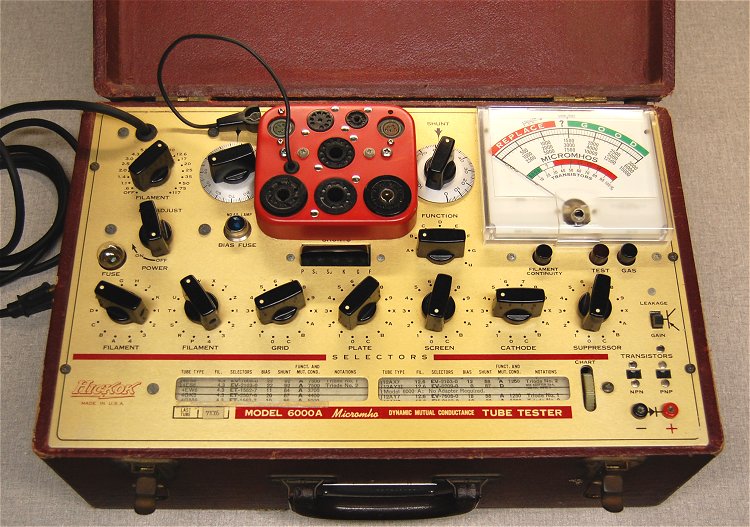
Okay. I powered everything down, and gave this development a little thought. The easiest thing to check would be the tubes in the final. One 12BY7A and two 6146‘s. I pulled the tubes and tested them on my Hickok 6000a tester – they were perfectly fine, happy little tubes. That wasn’t it.
In thinking over what I had already checked, I realized there was one resistance measurement I had not bothered to make. There was a footnote in the resistance check instructions that that stated with the meter in the Ip position, and the mode switch in the Spot position, one of the outputs from the VFO should be at ground. I had not checked this, since most of the resistance checks were to insure that there was not a short to ground at the test point. I made the neglected test, and instead of a short to ground, I had an open – infinite resistance. There was something wrong with the switch!
Pulling out my trusty can of Radio Shack Control/Contact Cleaner and Lubricant, I went after all the switches and pots in the rig. My technique is the nest each control in a wad of paper towelling on all sides, and then literally blast the crap out of it while moving the control through its entire range repeatedly. This cleaner foams up a la Scrubbing Bubbles for electronics, and I have had good success with it before. The key is to be sure to mop up any excess; let the control sit for while and then wipe it down again. It’s a good idea to check the next day for any residue which may have seeped out.
After the control cleaning exercise, everything worked fine. The plate idle current looked a tad low, so I adjusted it according to the manual, and after that the meter indication was spot on. I did not re-neutralize the tubes or realign the output, and these steps did not appear to be necessary.

It’s alive!
After figuring that out, there was one more small issue to deal with. The HX-1681 manual describes a simple mod to the HR-1680 receiver to better match audio levels for the sidetone produced by the transmitter. This involved changing a 33k ohm resistor on the audio board of the receiver for a 100k Ohm value, and adding a 10k ohm resistor in series with one on the audio lines to the volume control. I found both these resistor values in our local RadioShack in Oneonta NY, and made the change “in the field” so to speak, as the receiver was already at my upstate QTH.
I was ready to install and test the transmitter with its companion 1680. I needed three shielded male-male RCA phono plug cables to connect receiver mute, sidetone, and receive antenna. Although the manual calls for coax with phono plugs to connect the receive antenna, the shielded audio cable (also from RadioShack) seems to work fine; I’ll replace it with coax if I notice any problems. The initial tune-up into a dummy load went well, but I was a little disappointed to hear hum in the audio out when the transmitter was keyed. On a hunch, I grounded the transmitter and receiver chassis together, and the hum disappeared.
My habit is to use an end fed half wave antenna cut for 40 meters, with a 4:1 balun and a manual antenna tuner at the upstate QTH. This works fine with my modern solid state rigs, but the setup is a bit cumbersome for use with output tank of the a tube transmitter. There is a concern that there might be harmonics in the output that are stronger than the current FCC regulations allow; these are more stringent now than when these tube transmitters roamed the earth. Using a resonant antenna is best, but a tuner also helps clean up the signal.
The problem is the chicken-and-egg relationship between the transmitter output tank and the tuner. When you tune the transmitter for maximum RF out, you are adjusting the tank to load to whatever it sees. If that happens to be an antenna tuner that you then adjust for lowest SWR, you are de-tuning the transmitter tank…
Here’s my solution to this conundrum (since I really can’t set up a resonant antenna given the configuration of my upstate shack): I load up the transmitter into a resonant dummy load, back off the plate current a lot, then switch to an auto-tuner connected to whatever antenna configuration I have set up. When all the chatter subsides, the auto-tuner has got my “random wire” looking as resonant as it’s going to get. I can then bring up the transmitter power and tweak the tank. The perfect fusion of retro and space age technology.
With everything installed and working, it turned out that propagation was not great that weekend with minor magnetic storms going on. I did see my signal in RBN, so I know I’m getting out. There just wasn’t enough time that weekend to make a QSO though.

RBN can hear me!
There will be some further embellishments on this station in the coming months, but I’m pretty excited. There are lots of retro radio events coming up: Straight Key Night, Novice Rig Roundup, the Classic Exchange and others. I am really looking forward to putting my twins through their paces.
73
de N2HTT

Typical old radio adventures! Well done. Those units are just so beautiful.
Pingback: Novices. | 73, de N2HTT
Pingback: A cootie? | 73, de N2HTT